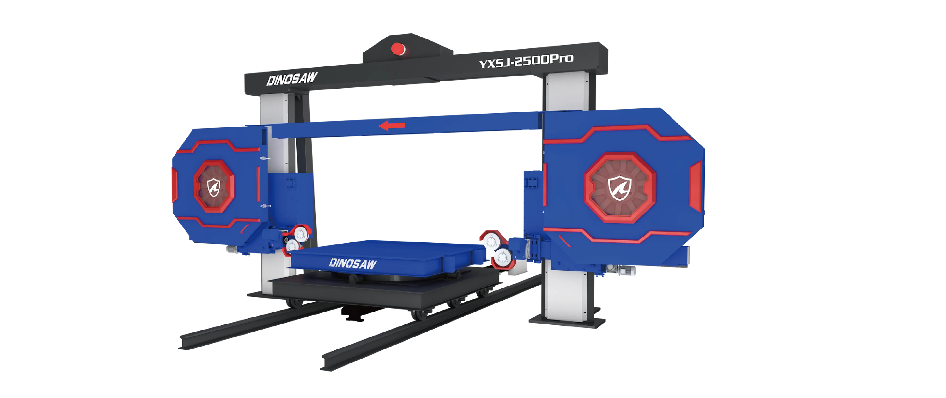
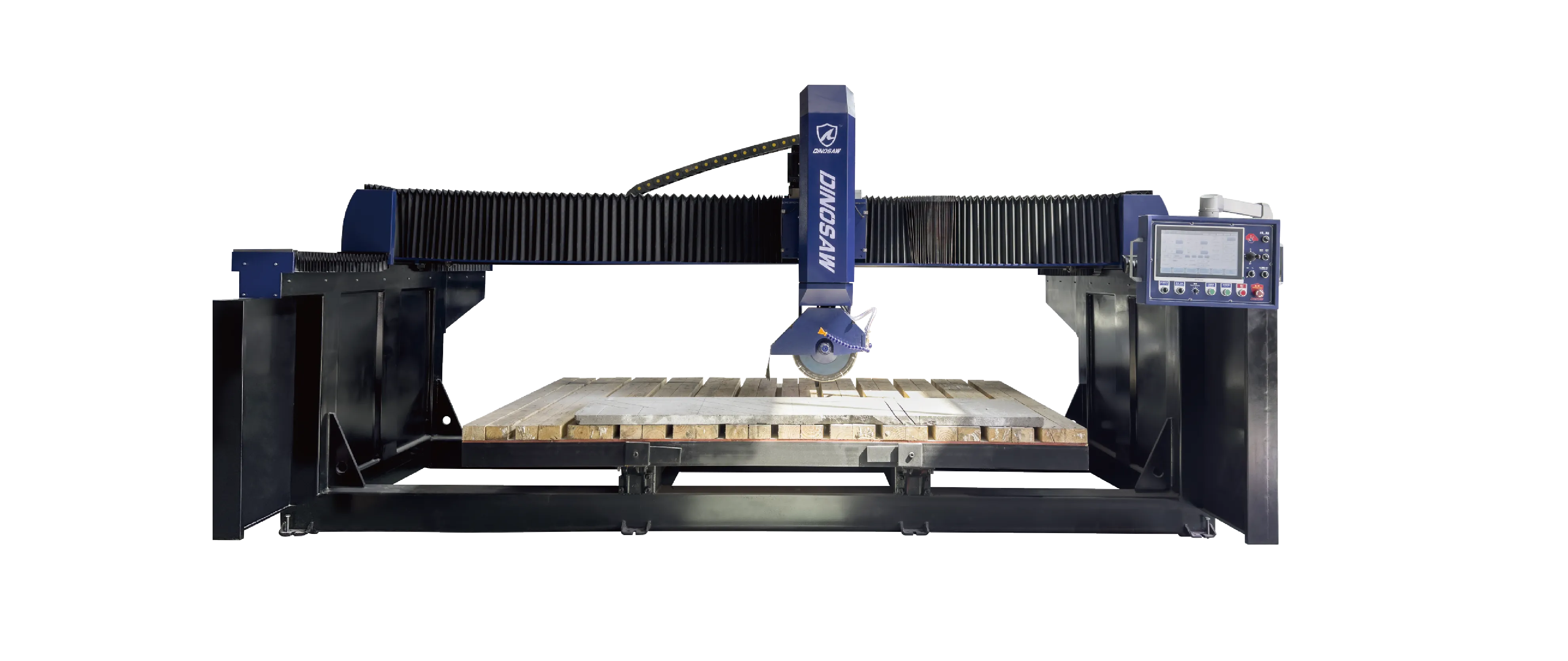
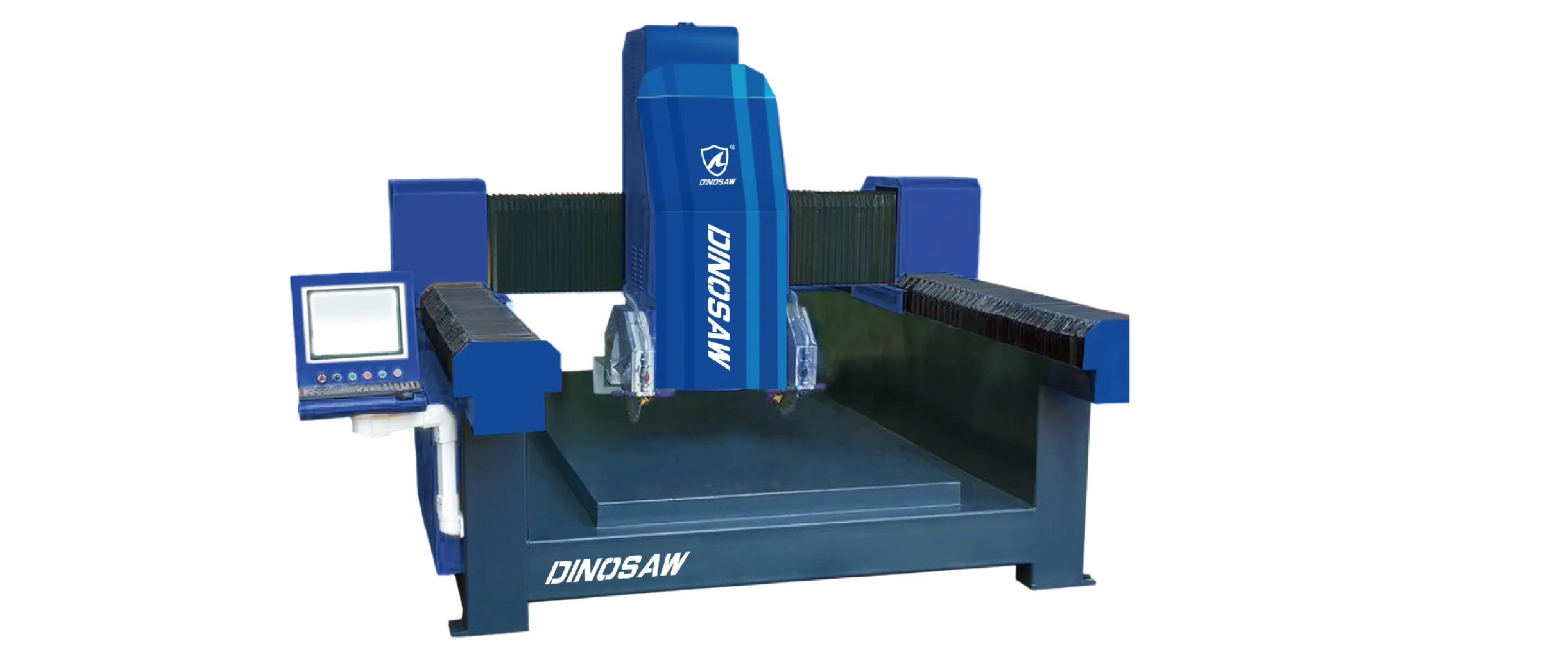
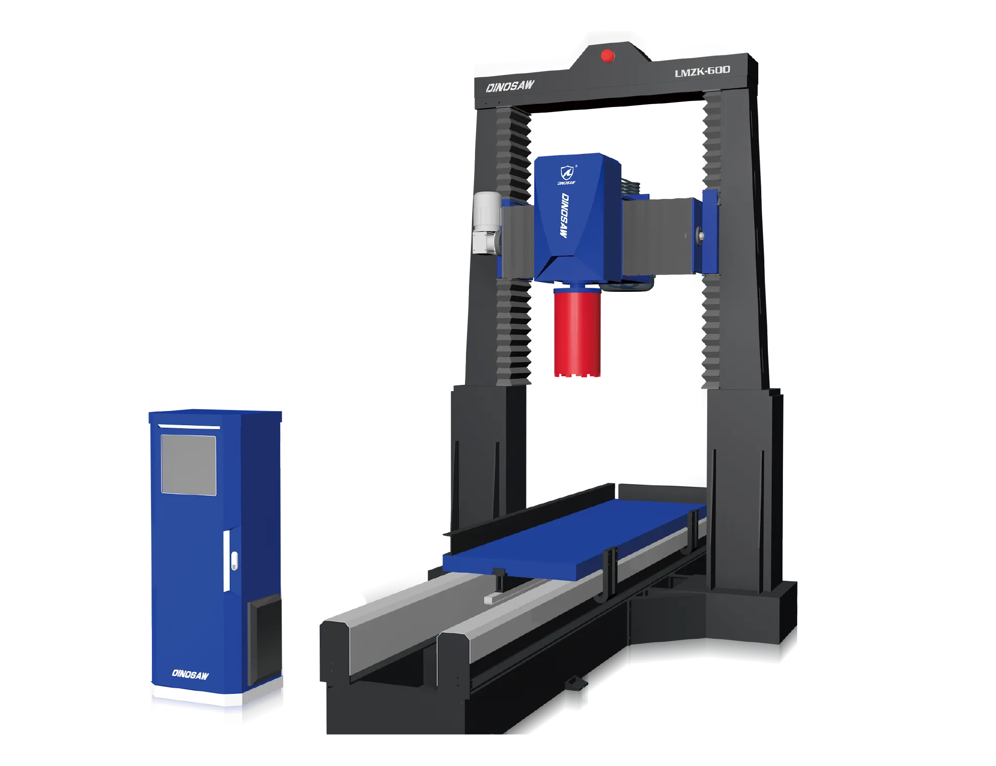
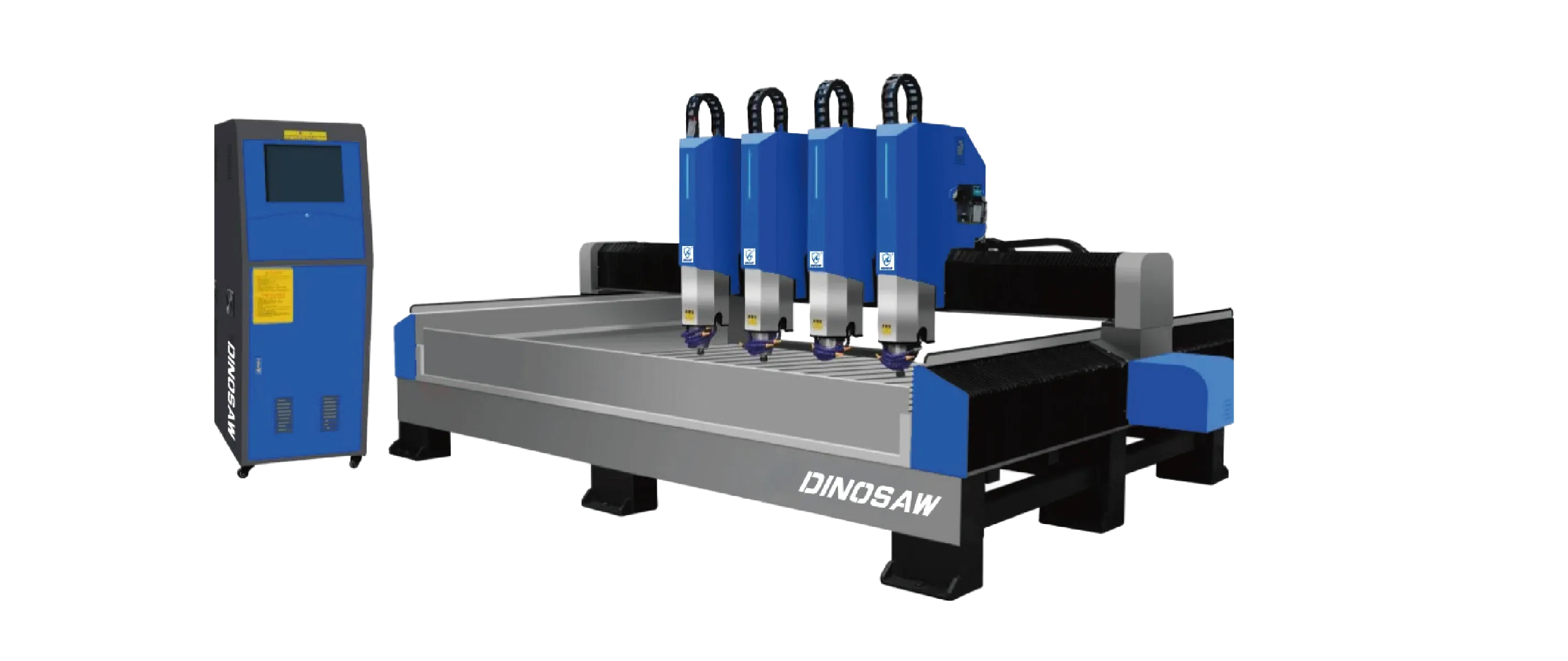
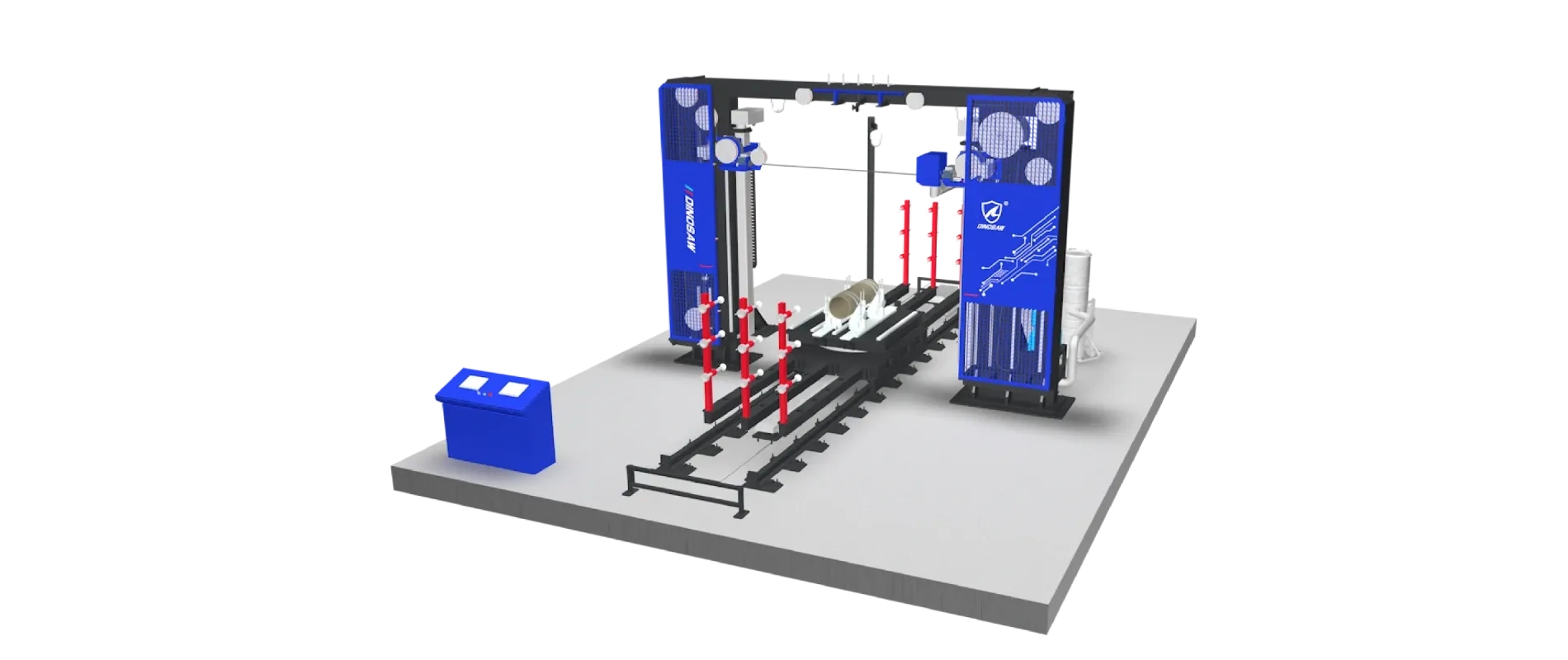
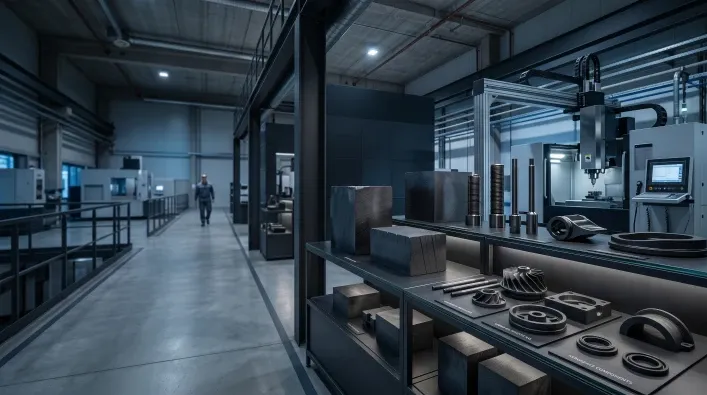
Understand the components, operating ranges, recipes, failure signs, and PLC/fieldbus options for reliable stone cutting with a 5-axis bridge saw.

For engineers and maintenance teams, reliable production depends on predictable equipment performance. Understanding the core architecture, component operating ranges, and potential failure modes of a 5-axis CNC bridge saw is critical for maximizing uptime and ensuring cut quality. This technical guide breaks down the DINOSAW WZQJ-5N, providing the details needed for effective integration, operation, and maintenance planning.

Contact our technical team to discuss integration options and detailed parameter settings for your specific materials.

The machine's design centers on a monoblock bridge structure supporting a head with 0–90° A-axis tilt and 360° C-axis rotation. This is powered by a high-precision 18.5 kW spindle and guided by the DDX CNC control system, which directly imports DXF/DWG files. Key subsystems include integrated camera nesting, a water-cooling system, and a vacuum-based material handling system.

System Architecture Overview of 5-axis CNC bridge saw

The 5 axis bridge cutting machine is a cohesive system where mechanical, electrical, and software components work in unison. A deeper look at its structure is available in our Anatomy of a CNC Bridge Saw guide.

  • Mechanical Frame: A rigid monoblock structure minimizes vibration and simplifies installation.
  • Axes and Drives: High-precision servo motors and guides control the X, Y, Z, A, and C axes for accurate interpolation.
  • Spindle and Blade: The core cutting unit, equipped with a powerful motor and adaptable blade mounting.
  • Cooling and Water Management: A closed-loop or open system delivers coolant to the blade to prevent overheating and control dust.
  • Vision and Control Systems: An industrial camera for slab capture and the DDX controller for executing G-code from CAD files.
  • Tooling and Handling Options: Optional upgrades include a milling tool for drilling/polishing (5+1-axis) and a CAM-integrated vacuum suction system for repositioning parts (5+2-axis) (manufacturer-reported).

5 axis Stone Saw Key Components and Operating Ranges

Understanding the operational limits of each component is vital for programming and maintenance. For a broader market comparison, see our guide on the Best Stone CNC Machine Types.

ComponentSpecification / RangeEngineering Note
SpindleMotor power: 18.5 kW (for Ø600 mm blade model) / 22 kW (for Ø800 mm blade model); RPM window: per blade manufacturer chart, calibrated on-site.RPM must match blade diameter and material hardness to avoid glazing or excessive wear.
Blade DiameterØ600 mm (23.6 in) standard; Ø800 mm (31.5 in) optionalLarger blades allow for deeper single-pass cuts but require adjusted feed rates.
Axis StrokesX: 3.2 m (126 in); Y: 2.0 m (78.7 in); Z: 0.45 m (17.7 in)Defines the maximum workable slab dimensions and cutting depth.
A-Axis (Tilt)0–90°Enables miter cuts and angled drilling operations.
C-Axis (Rotation)0–360°Allows for curved cutting and profiling without rotating the slab.
Vacuum HandlingMax suction capacity: 200 kg (≈ 440 lb)Suction integrity is critical. Check seals and pump pressure regularly.
Camera SystemHD Camera with laser positioningAutomatically measures slab thickness and tool size for optimized nesting.
Tooling Options (Optional)Milling tool (5+1-axis config); Typical milling feed: 0.8 m/min (≈ 31.5 in/min)Adds capabilities for drilling, edge polishing, and other milling operations.
Handling Options (Optional)CAM-integrated vacuum suctionAllows for safe repositioning of parts mid-process and helps avoid over-cutting.

Note: The machine can be configured as a standard 5-axis saw, a 5+1-axis saw (with milling tool), or a 5+2-axis saw (with milling tool and vacuum suction), depending on selected options (manufacturer-reported).

Common Failures and Mitigation

Early diagnosis of common issues can prevent material waste and costly downtime.

  • Symptom: Chipping or corner cracks in material.
    • Likely Causes: Insufficient coolant flow, worn-out blade segments, or excessive feed rate.
    • Mitigation: Check coolant nozzles for clogs, inspect blade for glazing/wear, and reduce feed speed on final passes.
  • Symptom: Axis misalignment or dimensional inaccuracy.
    • Likely Causes: Vacuum system slippage on polished surfaces, mechanical play in the bridge, or incorrect tool compensation values.
    • Mitigation: Verify vacuum pressure, run axis calibration routines, and double-check tool offset data in the controller.
  • Symptom: Excessive vibration during cutting.
    • Likely Causes: Unbalanced blade, worn spindle bearings, or a non-level machine foundation.
    • Mitigation: Inspect blade for damage, listen for bearing noise, and confirm the machine is level.

System Compatibility and Integration

The 5 axis bridge cutting machine is designed to integrate into modern digital fabrication workflows.

  • Data Exchange: Supports direct import of DXF and DWG files, eliminating the need for manual programming of complex shapes.
  • PLC and Fieldbus: Options for integration with factory-level monitoring systems via protocols like OPC UA, Profinet, or Modbus are available on request; supported protocols can be provided by the technical team. This enables real-time production data logging.
  • Safety Interlocks: Includes standard safety circuits for emergency stops and perimeter guarding, which can be tied into a plant-wide safety system. Proper grounding and EMI shielding are implemented to ensure stable operation.

Typical Starting Parameters (to be validated on site)

Optimal settings vary based on material properties, which can be verified using ASTM standard test methods. The following are conservative starting points to be refined on-site.

Granite (Medium Hardness)

  • RPM: set per blade chart for granite
  • Feed: start conservative and increase as kerf stays clean
  • Depth-per-pass: shallow passes for clean edges

Engineered Quartz

  • RPM: per blade chart for quartz
  • Feed: moderate
  • Depth-per-pass: use multi-pass to reduce heat buildup

Ceramic/Sintered Stone

  • RPM: lower, per tooth spec
  • Feed: slow and steady
  • Depth-per-pass: thin passes to prevent microcracks

Frequently Asked Questions

What is the safe RPM window for a Ø600 mm blade in quartz?

The safe RPM for a Ø600 mm blade in quartz varies by blade and material; consult the blade supplier’s chart and adjust to prevent scorching or chipping. Operating at too high an RPM can cause resin scorching and premature blade wear, while too low an RPM can lead to chipping.

How does automatic tool compensation affect miter accuracy?

Tool compensation automatically adjusts the tool path to account for the blade's diameter and wear. For miter cuts, this ensures that the cutting point remains precisely on the programmed line, resulting in tight, accurate seams without manual adjustments.

Can OPC UA be used for production data logging from the saw?

Yes, with the optional interface kit; the machine can expose data points via OPC UA. This allows you to log key production metrics like cycle times, error codes, and material usage into a factory-wide SCADA or MES system for analysis.

What coolant flow rate is needed to prevent ceramic chipping?

A generous and consistent coolant flow is critical for cutting brittle materials like ceramic. The goal is to ensure full flooding of the cut zone on both sides of the blade; increase flow until debris clears instantly and no steam forms. This is a key control measure advised by NIOSH safe work practices for silica dust suppression.

How do you calibrate the A and C axes for the 5-Axis CNC Bridge Saw?

Calibration is performed using the machine's HMI control panel, following a guided procedure. It typically involves moving the axes to known reference points or using a calibration fixture to set the zero positions. Regular calibration is essential for maintaining the machine's manufacturer-reported ±0.05 mm precision.

What causes cracks at the corners of sink cutouts?

Corner cracks are usually caused by concentrated stress. This can result from a sharp, 90-degree toolpath without a radius, too fast a feed rate when changing direction, or insufficient cooling. Using a toolpath with a small radius in the corners and slowing down the feed rate can mitigate this. The decision to use a bridge saw over other technologies for this work is detailed in our Bridge Saw vs. 5-Axis CNC Saw investment guide.